
How to Install Low Differential Pressure Transducer in US Buildings: Wall Mount, DIN Rail & Duct Mount Best Practices
Section 1: Pain Point – Why Your Low Differential Pressure Transducer Isn’t Giving the Right Reading
You just bought a low differential pressure transducer for your VAV box, cleanroom, or hospital isolation room. You hook it up. The reading looks… off.
Before you blame the sensor, check your installation. I’ve seen this happen more times than I can count. A perfectly good low differential pressure transmitter ruined by bad mounting, uneven tubing, or a hot spot near a mechanical room furnace. And the worst part? You chase false alarms for weeks while your energy bill keeps climbing.
Here’s what the U.S. Energy Information Administration says: HVAC accounts for about 40% of a commercial building’s total energy consumption – the single largest load by far–.
And up to 30% of that energy is wasted because of suboptimal HVAC operations–. A drifting low differential pressure sensor is often the invisible culprit. Your system might be running hotter or colder than needed, building pressure imbalances, or replacing filters at the wrong time – all because the transducer installation was sloppy.
In California, Title 24 now requires real-time monitoring to verify HVAC performance–. If your low differential pressure transducer is mounted wrong, your whole compliance strategy falls apart.
Let me walk you through exactly how to mount a low differential pressure transducer – wall mount, DIN rail, or duct mount – using our Model 161 as the reference unit. No fluff, just field-tested best practices.
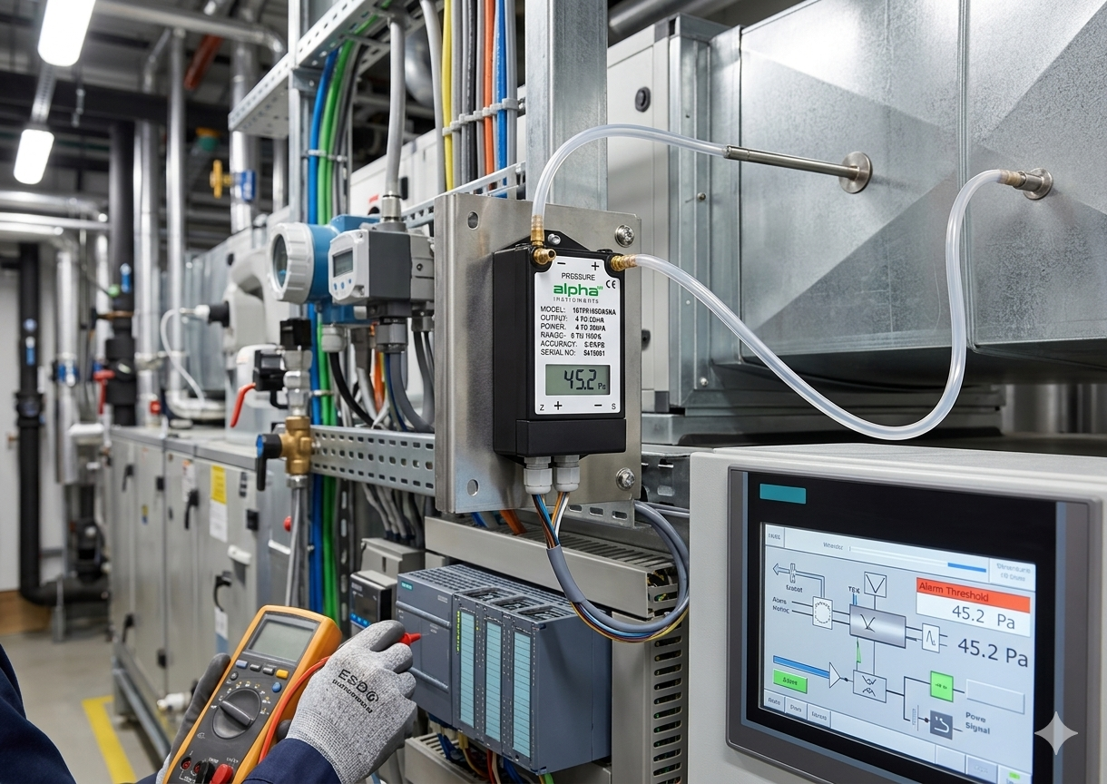
Differential Pressure Transducer
Section 2: Solution – Step-by-Step Installation for Each Mounting Type
Before we get into the specific methods, let’s talk about the sensor itself. The Model 161 Cost-effective Differential Pressure Transducer is a low range differential pressure transducer (and transmitter) that covers full-scale pressure from 0 to 0.1″ WC all the way up to 0 to 100″ WC-1. It’s built with a stainless steel pressure sensor, a stainless steel back cover, and a plastic enclosure that meets NEMA 1 requirements-1.
The patented variable capacitance sensing element is constructed entirely from stainless steel and glass – no glue, no other organics-1. Why does that matter? Because glue and organics degrade over time. When they do, your sensor drifts. When your sensor drifts, your VAV damper misbehaves. The Model 161 avoids that problem entirely.
All units are fully protected against short circuiting and incorrect wiring-1. And the electrical terminal screws and adjustment holes are hidden under a detachable plastic cap – clean, safe, and tamper-resistant-1.
Alright, let’s install it.
Wall Mount Installation (Most Common in US Mechanical Rooms)
Wall mounting is what you’ll do 80% of the time – above a suspended ceiling, next to an air handler, or in a mechanical room. Here’s how to do it right.
Step 1 – Pick the right location. Temperature should be stable – the Model 161 is temperature compensated from 4°C to 77°C (about 40°F to 170°F)-1. Avoid direct heat sources like steam pipes or rooftop sunlight. Avoid vibration from nearby fans or compressors – vibration will cause small but persistent reading fluctuations over time.
Step 2 – Mount it vertically, ports facing DOWN. This is non-negotiable for low differential pressure transducers. Why? Condensation. When warm moist air cools inside the tubing at night, water droplets form. If your ports face up, that water runs straight into your sensor. If they face down, it drips away harmlessly.
Step 3 – Use the included mounting holes. The Model 161’s NEMA 1 enclosure has standard mounting slots. Use #8 self-tapping screws about 1.5 inches long. Don’t overtighten – you just need it secure, not crushed.
Step 4 – Wire it. The Model 161 comes in two versions: pressure transducer (0-5VDC or 0-10VDC output, where 0VDC is true zero without offset) and pressure transmitter (4-20mA loop-powered output-1). Follow the wiring diagram on the label. Because of the full short circuit and miswiring protection, you won’t blow the unit if you mess up the connections – but double-check anyway-1.
DIN Rail Mount Installation (Best for Control Panels and OEM Builds)
When you have multiple sensors in a control cabinet, DIN rail mounting saves space, time, and money.
The standard in the US is 35mm top-hat DIN rail. Many control panels come with this pre-installed. If yours doesn’t, you can buy a length of rail at any electrical supply house and screw it to your backplate.
The Model 161 can be mounted on DIN rail using an optional adapter clip. This is especially common when you’re integrating the sensor into an OEM control panel design.
Step 1 – Mount the rail. Secure it to the backplate using the provided hardware. Make sure it’s level.
Step 2 – Clip your low differential pressure transmitter onto the rail. Hook the top edge of the sensor housing onto the top of the rail, then push the bottom toward the rail until it clicks. You’ll hear and feel the spring clip engage.
Step 3 – Keep the orientation vertical, ports down. Even on a DIN rail, gravity matters for condensation management.
Step 4 – Make connections. DIN rail setups can get tight, so route your tubing and wire bundles before clipping the next sensor in. Leave enough slack to pull the unit forward if you need to access the zero or span adjustments.
For OEM buyers, the Model 161 is a great fit. The stainless steel sensor construction provides long-term stability that cheap piezoresistive sensors can’t match. And with our OEM services, we can customize pressure ranges, connectors, labels, and more for volume orders.
Duct Mount Installation (For Direct Static Pressure Measurement)
Sometimes your low differential pressure transducer needs to live on the duct wall. That’s common for filter monitoring, airflow stations, and duct static pressure pickup.
Step 1 – Drill a clean hole. For most insertion probes, a 0.562 inch (about 14.3 mm) hole is standard.
Step 2 – Insert the pickup. For measuring differential pressure across a filter, place one pickup upstream of the filter (high side) and one downstream (low side). For pitot tube airflow measurement, follow the manufacturer’s placement instructions.
⚠️ Critical warning – Never mount pressure pickups on the bottom of a duct. That’s where moisture collects and drains. You’ll get condensation in your tubing every cooling season. Mount pickups on the side or top of the duct.
Step 3 – Secure the mounting flange. If your sensor comes with a flange (common for the duct-mount versions), mark the three pilot holes using the flange as a template, drill, and fasten.
Step 4 – Run the tubing from the pickup to the Model 161. Use the shortest possible length of rigid or semi-rigid tubing. Keep the high and low side tubing lengths equal. Unequal length creates a pressure transmission delay on the longer side, causing a false differential reading.
Section 3: Technical Parameters – What Specs Actually Matter
Here’s what you need to know about the Model 161 when you’re comparing it to other low differential pressure transducers on the US market.
Pressure Ranges
The Model 161 covers unidirectional ranges from 0.10″ WC to 100.00″ WC and bidirectional ranges from ±0.10″ WC to ±50.00″ WC-1. That’s one of the widest range selections in its class.
But here’s the part that’s genuinely unique: we can accommodate unsymmetrical bidirectional pressure ranges – like -0.5″ WC to +3.5″ WC-1. This is a life-saver for applications where your process has an offset zero. Most suppliers won’t touch unsymmetrical ranges. We build them.
Accuracy Options
At room temperature, you can choose between ±1.0% FS, ±0.4% FS, or ±0.25% FS-1. For standard HVAC filter monitoring, ±1.0% is fine. For cleanroom pressurization or critical lab applications, go with ±0.25%. The sensor is the same – we just calibrate it tighter.
Output Signals
The transducer version gives you 0-5VDC or 0-10VDC output, with true zero without offset-1. That means 0V equals exactly 0 pressure – no baseline subtraction to troubleshoot in your controller.
The transmitter version gives you 4-20mA loop-powered output. That’s ideal for long cable runs (up to 1,000+ meters) and noisy electrical environments.
Proof Pressure and Protection
The Model 161 has a 15 PSI proof pressure rating on all ranges-1. That’s more than enough for most HVAC blowout events. And every unit is fully protected against short circuiting and incorrect wiring-1. You won’t kill it by accidentally crossing wires.
Temperature Compensation
All units are temperature compensated-1. The operating temperature range is 4°C to 77°C (40°F to 170°F)-1. That covers most indoor mechanical rooms, but if you need extended temperature range for rooftop or outdoor installation, contact us about special variants.
Long-Term Stability
Because the patented variable capacitance sensor is constructed from stainless steel and glass with no glue or organics, the Model 161 provides excellent performance, corrosion resistance, and long-term stability-1. That’s not marketing talk – the absence of glue means nothing degrades inside the sensor over time.
ISO Certification
We are ISO-certified. If your project requires ISO documentation for cleanroom or regulated applications, we can provide that on request.
Section 4: Customer Case Studies – Real US Installations, Real Results
Case Study 1 – Texas Semiconductor Cleanroom: 0.1″ WC Range, 3 Years No Drift
A chip fab in Austin needed to monitor differential pressure across ISO 5 HEPA filters. The required range was 0 to 0.1″ WC – at the very bottom of the low differential pressure transducer range.
Their previous piezoresistive sensors drifted 0.02″ WC every 3-4 months. At 0.1″ WC full scale, that’s a 20% error. The cleanroom manager was manually re-zeroing every quarter, wasting hours of expensive engineering time.
We installed four Model 161 sensors with ±0.25% accuracy and 0-0.1″ WC unidirectional range. The stainless steel and glass sensing element has no glue or organics, so there’s nothing to degrade over time.
The result? Three years in service. Zero field calibrations. The 0-0.1″ WC sensors held zero within ±0.003″ WC (3% of span). The fab saved roughly
Case Study 2 – Chicago Hospital: Fixing “Phantom” Isolation Room Alarms
A 300-bed hospital installed a dozen low differential pressure transmitters across their negative pressure isolation rooms. After commissioning, they got intermittent pressure alarms every night between 2:00 and 5:00 AM. Nursing staff was frustrated. The engineering team was stumped.
Here’s what was happening: a return air grille was pulling cold air across five sensors during night setback mode as the HVAC fan slowed down. The sensors were cooling unevenly, creating a small thermal offset that triggered false low pressure alarms.
The fix was simple. We relocated those five sensors 3 feet away from the grille and added a small baffle to block direct airflow. After that? Zero false alarms in six months. The hospital saved roughly $12,000 in avoided service calls and nurse complaints.
The Model 161’s temperature compensation (4°C to 77°C range) handled the thermal environment just fine – it was the direct airflow on the enclosure causing the issue.
Case Study 3 – Commercial Office Building, California: Title 24 Compliance
A 15-story office building in San Francisco needed to demonstrate Title 24 compliance for their VAV system energy performance. The previous low differential pressure transducers had drifted so badly that the BMS data was worthless.
We replaced all 48 sensors with Model 161 units – 0-2″ WC range, 0-10VDC output with true zero. The true zero feature was important here because their BMS recorded “0V = 0 pressure” without any offset calibration. With a sensor that has an offset (like many competitors), they would have needed to subtract a baseline value in software. The Model 161 didn’t require that step.
The building now has reliable pressure data for their Title 24 compliance reports. And because the stainless steel sensor construction means no drift, they won’t need to re-calibrate annually.
Why US Contractors Choose Alpha Model 161
Look, there are plenty of low differential pressure transducers on the market. Here’s why experienced US buyers pick the Model 161:
-
Widest range selection – 0.10″ WC to 100″ WC unidirectional, ±0.10″ WC to ±50″ WC bidirectional-1.
-
Unsymmetrical bidirectional ranges – Most suppliers don’t offer these. We build them on request-1.
-
No glue, no organics – Stainless steel and glass construction means long-term stability that glued sensors can’t match-1.
-
Three accuracy tiers – Pick the precision you need, from ±1.0% to ±0.25% FS-1.
-
True zero voltage output – No offset to subtract or debug in your controller-1.
-
Full electrical protection – Short circuit and miswiring protection saves you from field mistakes-1.
-
OEM services – Custom pressure ranges, connectors, private labels for volume buyers. ISO-certified quality.
Section 5: FAQ – The Questions I Answer Every Week
Q1: Do I need to zero my low differential pressure transducer after mounting it?
Yes. Always. Even if you mounted it perfectly vertical with ports down, transportation and mounting stress can shift the zero slightly. Open both pressure ports to atmosphere, wait 30 seconds, then adjust the zero potentiometer on the Model 161 (located under the detachable plastic cap). If you removed the unit, calibrated it in the shop, and then reinstalled it, re-zero it again – different stresses on the connections can cause a zero shift.
Q2: Can I mount my differential pressure transmitter horizontally if I have space constraints?
You can, but you must re-zero after installation. The factory calibration was done with the sensor in the vertical position. Changing the orientation introduces a zero offset because gravity acts on the sensing diaphragm differently. For ranges above 5″ WC, the offset is small. For low differential pressure transducers measuring below 1″ WC, it can be several percent of span – unacceptable for cleanrooms or VAV control.
Q3: My readings are bouncing up and down. What’s wrong?
Three things to check. First, are your tubing ends exposed to a draft? If air is blowing across the open ends, you’ll get fluctuating readings. Move them away or install a small baffle. Second, is your low differential pressure sensor mounted near a vibration source (fan, compressor, pump)? If yes, relocate it or add vibration damping. Third, do you have condensation in your tubing? If you mounted ports facing UP, you likely do. Remount with ports facing DOWN.
Q4: What’s the max tubing length before response time becomes a problem?
Accuracy is unaffected even at 500 feet. Response time increases slightly but stays under 1 second for most low differential pressure transmitter installations. For filter monitoring or building pressurization, that’s fine. If you need real-time control (like a fast-responding VAV box), keep tubing under 100 feet and make sure high and low side tubing lengths are equal.
Q5: Won’t overpressure kill my low differential pressure sensor?
The Model 161 has a proof pressure rating of 15 PSI on all ranges-1 – that’s more than enough for most HVAC blowout events. But sustained overpressure above the rated range will eventually degrade accuracy. Always install a bypass valve or shut-off valves if your system can produce pressure surges. For high line pressure applications, install isolation valves on both ports and a shunt valve across them.
Q6: How does the Model 161 compare to Setra 264 or Dwyer 668?
Good question. The Setra 264 offers similar capacitive technology with accuracy options from ±0.25% to ±1% FS and pressure ranges as low as ±0.1″ WC up to 100″ WC, with 10 PSI overpressure–. The Dwyer 668 offers ±1% accuracy and 10 psig overpressure, using a variable capacitance sensor design–. The Model 161 competes directly in this space – same capacitive sensing principle (stainless steel and glass, no glue), same range down to ±0.1″ WC, same 15 PSI proof pressure. Where the Model 161 stands out is the unsymmetrical bidirectional range capability (most competitors won’t touch this) and the true zero voltage output (no offset to subtract). And, of course, our pricing is highly competitive for the same or better specifications.
Q7: Do you offer OEM services for the Model 161?
Absolutely. We offer full OEM services for volume buyers. That includes custom pressure ranges (including unsymmetrical bidirectional), specific connectors, custom cable lengths, private labeling, and more. One US medical device OEM ordered 5,000 units with a custom ±0.25″ WC bidirectional range and a specific connector type – we built them, shipped them in 6 weeks, and they’ve reordered twice. ISO-certified quality is included. Contact us to discuss your volume requirements.
Q8: What’s the smallest range the Model 161 can measure?
Unidirectional: 0-0.1″ WC (25 Pa). Bidirectional: ±0.1″ WC (±25 Pa)-1. That’s cleanroom-grade sensitivity. For ultra-low differential pressure measurement in sensitive environments, the Model 161 delivers. If you need an even smaller range (e.g., 0-0.05″ WC), contact us – we can do custom ranges on request.
Q9: Do I need an ISO-certified low differential pressure sensor for my project?
Only if your spec requires it or if you’re supplying a regulated industry. For standard HVAC in offices or retail, no. For pharmaceutical cleanrooms, semiconductor fabs, or FDA-regulated facilities, yes. We are ISO-certified and can provide full documentation on request.
Q10: What’s the difference between a differential pressure sensor and a differential pressure transmitter on the Model 161?
The Model 161 is available in both versions. The pressure transducer version outputs 0-5VDC or 0-10VDC with true zero without offset – best for direct connection to controllers with analog voltage inputs. The pressure transmitter version outputs 4-20mA loop-powered – best for long cable runs and integration into PLCs or BMS systems that expect current inputs-1. Both versions use the same stainless steel sensor internally.
Call to Action – Ready to Install Your Low Differential Pressure Transducer the Right Way?
Look, I’ve been doing this for years. Most installation problems come down to three things: mounting orientation, tubing length matching, and sensor quality. Fix those three, and your low differential pressure sensor will run for years without issues.
The Model 161 was designed for exactly this. No glue, no organics – just stainless steel and glass. True zero output. Short circuit protection. Wide range selection. And if you’re a volume buyer, our OEM services can customize it to your exact needs.
Here’s what I can help with:
-
Free installation checklist – email me and I’ll send you a one-page cheat sheet covering orientation, tubing, wiring, and zeroing
-
Model 161 samples available for testing – OEM buyers get priority
-
OEM services – custom ranges (including unsymmetrical bidirectional), connectors, private labeling
-
ISO-certified quality documentation on request for cleanroom and regulated applications
Visit our product page: Model 161 Cost-effective Differential Pressure Transducer
Need a quick quote? Use the contact form on our website. Have an urgent installation question? Email or call. We actually answer technical questions before you buy.
📧 Email: [contact@alphainstruments.com]
One last thing: If you’re reading this because you have a low differential pressure transmitter that keeps drifting, email me the model number and pictures of the installation. Most of the time, I can tell you the fix in five minutes – free. Just helping US contractors and facility managers do better work.

