Can Low Differential Pressure Transmitter Be Used for Flow Measurement with Pitot Tube? Yes, and Here’s How US Engineers Get It Right
Let me tell you about a call I took last month from a contractor in Texas who was trying to measure airflow in a 36-inch supply duct. He had spent $2,800 on a thermal dispersion flow station. Installed it. Calibrated it. It worked fine—for about three weeks. Then the sensors got dusty and the readings started drifting. He called me asking if there was a cheaper, more reliable way.
My answer? A $100 averaging pitot tube and a low differential pressure transmitter. That’s it.
The question comes up all the time in the US HVAC world: can a low differential pressure transmitter really do the job for airflow measurement? The short answer is yes. In fact, ASHRAE calls the pitot tube traverse the “generally accepted method of measuring airflow in ducts” , and “[t]he preferred method of measuring duct volumetric flow is the pitot tube traverse average as detailed in ASHRAE Standard 111”-10. The longer answer—which matters when you’re the one signing off on the installation—is that it works great as long as you pick the right transmitter and install everything correctly. A differential pressure transmitter paired with a pitot tube is a proven, low-cost way to measure airflow in US commercial buildings, and it’s been done successfully for decades.
Let me walk you through how this actually works, what can go wrong, and why our Model 162 Cost-effective Differential Pressure Transmitter might be exactly what your next US job needs.
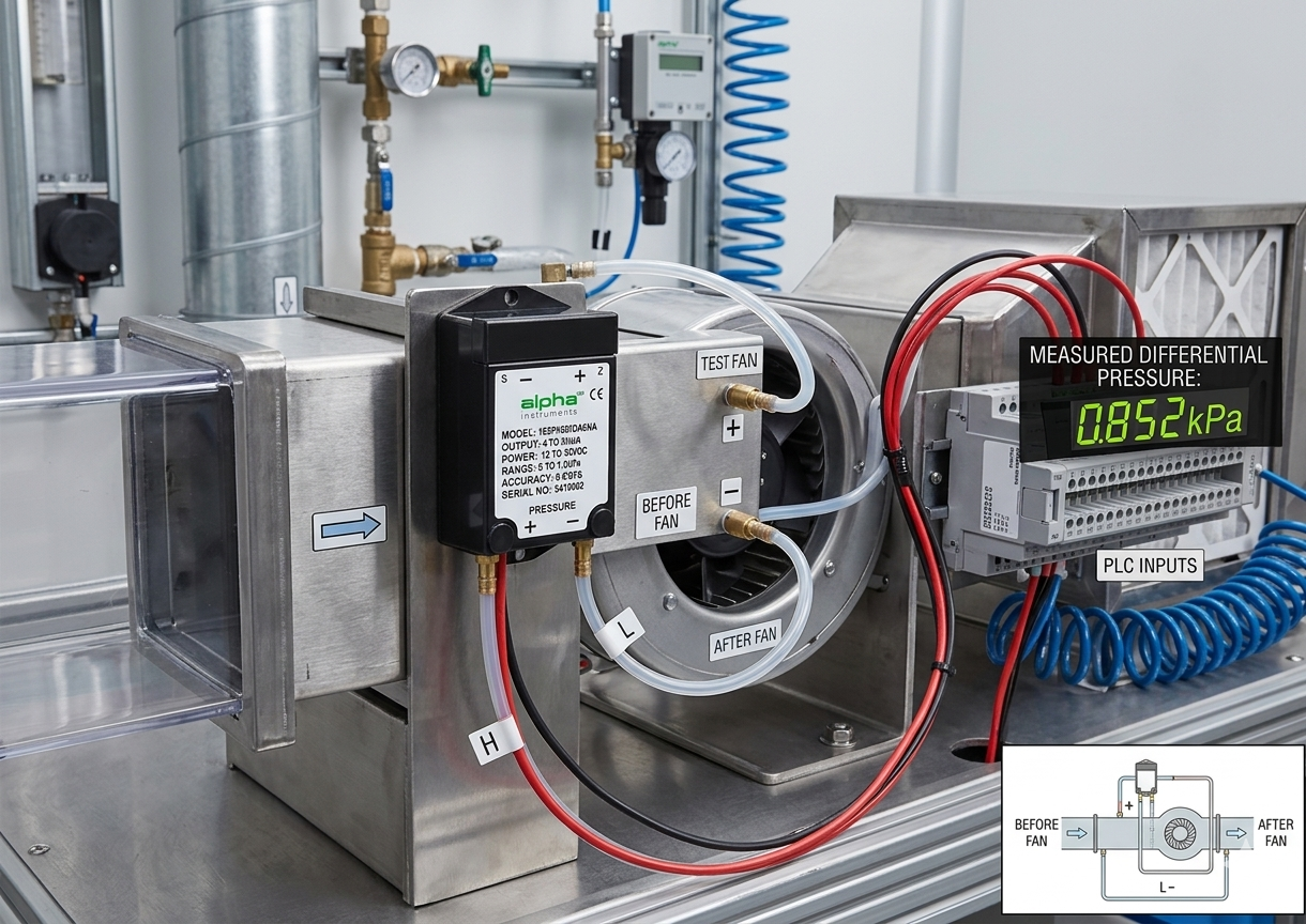
Differential Pressure Transducer
1. The Real-World Problem: Why Measuring Airflow in the Field Is Harder Than It Looks
You have a duct. Actually, you probably have dozens of them. Each one needs airflow data for VAV balancing, outside air verification, or Title 24 compliance reports. The “easy” solution is to buy commercial airflow stations—thermal dispersion units, ultrasonic meters, or those expensive averaging arrays. Those can run you 1,500to3,000 per point. On a job with 20 terminals, that’s real money.
The alternative? A pitot tube and a low differential pressure transmitter. Together, they cost a fraction of a commercial flow station. But here’s where contractors get into trouble.
The pitot tube generates something called velocity pressure. The formula is simple: velocity pressure is total pressure minus static pressure. The problem is that at typical duct velocities in US buildings—say, 500 to 2,000 FPM—that velocity pressure is tiny. At 500 FPM, velocity pressure is only about 0.015 inches of water column. That’s a whisper. A standard industrial pressure transmitter with a 10 psi range won’t even register it.
This is where the low differential pressure transmitter comes in. You need a differential pressure sensor that can accurately measure extremely small pressure differences at the low end of the range, and do it reliably over time without drifting. You also need stable zero performance because the differential pressure signal is proportional to the square of velocity—so a small error at low velocities gets magnified in your flow calculation. Let me show you how to do this right, using a low differential pressure transmitter that’s built for the job.
2. The Physics Behind It: How a Pitot Tube and a Low DP Transmitter Actually Work Together
A pitot tube has two ports. One port faces directly into the airflow—that’s the total pressure port. The other port measures static pressure, usually through small holes on the side of the tube. The low differential pressure transmitter measures the difference between these two pressures. That difference is the velocity pressure.
Here’s the key formula you need to remember. Flow velocity (in feet per minute) equals 4,005 times the square root of the velocity pressure (in inches W.C.). Written out: V = 4005 × √(velocity pressure). Then airflow in CFM equals velocity times the duct cross-sectional area in square feet: CFM = V × A-21-22.
Why is the constant 4,005? It comes from standard air density at 70°F and 29.92 inHg. If you’re working at high altitude—say Denver—you’ll need to adjust for lower air density. But for most US HVAC work, 4,005 is what you use. British thermal unit BTU, cubic foot per minute CFM, inches of water column—these are the units every US mechanical engineer and contractor works in.
Let me give you a real example from a job I helped with last year. A contractor measured a velocity pressure of 0.75 inches W.C. in a round duct. Here’s his math: √0.75 equals 0.866. Multiply that by 4,005, and you get 3,468 feet per minute. The duct was 18 inches in diameter, which gives a cross-sectional area of 1.77 square feet. So 3,468 FPM times 1.77 square feet equals 6,128 CFM-21-23.
Now here’s the catch. That velocity pressure signal is non-linear. Double the airflow, and the velocity pressure quadruples. So if your low differential pressure transmitter outputs a linear 4-20mA or 0-10V signal proportional to pressure, you or your BMS still need to take the square root somewhere. Some contractors handle this in their building automation system. Others prefer transmitters with built-in square root extraction—though that feature is more common on process-grade DP transmitters than on HVAC-grade units. Either approach works as long as you remember to do the math and not apply the square root twice.
The other catch is zero stability. If your low differential pressure transmitter drifts by just 0.01 inches W.C. at the low end of its range, that small error can cause a significant airflow miscalculation at low flow conditions. For a velocity pressure of 0.04 inches W.C., a 0.01-inch drift puts you off by 25% on ΔP, and you’re off by about 12-13% on calculated flow. That’s why the right low differential pressure sensor matters more than most contractors realize. A low differential pressure transmitter with excellent long-term zero stability—like our Model 162, which uses a variable capacitance sensing element built from stainless steel and glass with no glue or organics—will drift much less over time than a cheap piezoresistive sensor-1.
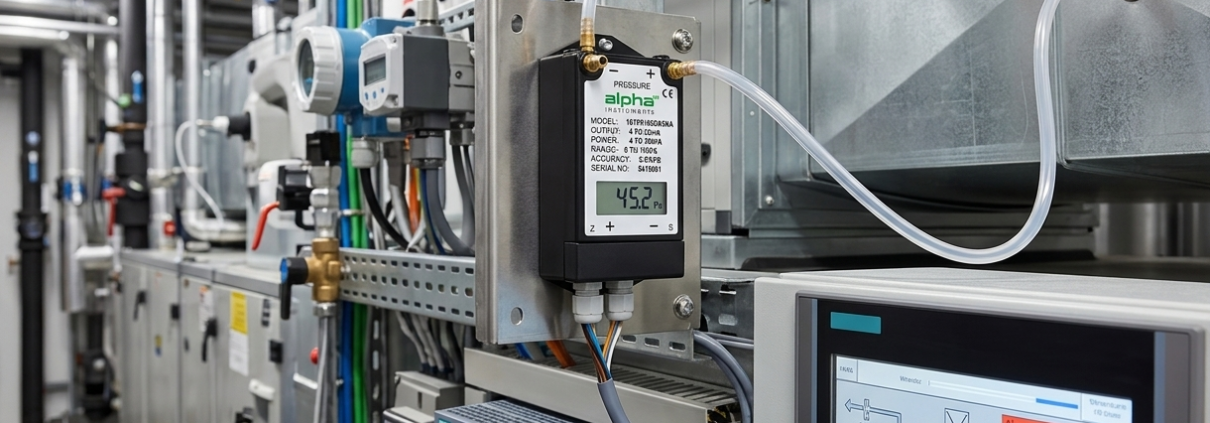
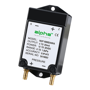
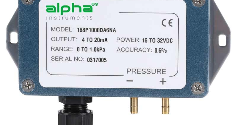
3. The Product: Alpha Instruments Model 162 Cost-effective Differential Pressure Transmitter
So what exactly should you look for in a low differential pressure transmitter for pitot tube flow measurement?
The Model 162 Cost-effective Differential Pressure Transmitter was designed with US HVAC contractors and OEM buyers in mind. It covers unidirectional ranges from 0.10 inches up to 100 inches of water column and bidirectional ranges from ±0.10 inches up to ±50 inches of water column-1. For pitot tube work, I usually recommend the 0-0.5 or 0-1 inch W.C. range for medium to high velocity ducts. If you’re measuring very low velocities—say 400 to 800 FPM—you’ll want the 0-0.1 or 0-0.25 inch range to get enough resolution at the bottom of the scale.
Accuracy is another critical factor. The Model 162 offers three accuracy options at room temperature: ±0.25%, ±0.40%, or ±0.60% of span-1. For most HVAC airflow measurement, ±0.60% is perfectly adequate. But if you’re working in a cleanroom, a laboratory, or a pharmaceutical facility that requires tight differential pressure control, spring for the ±0.25% version. The extra precision will pay for itself the first time you don’t get a false low-flow alarm.
The sensor itself is what makes the Model 162 different from cheap alternatives. The patented variable capacitance pressure sensor is constructed from stainless steel and glass—no glue, no other organics-1. Why does this matter? Because glue and organics degrade over time, especially in environments that cycle through temperature and humidity changes. When that happens, the zero point of your low differential pressure transmitter drifts. With a stainless steel and glass sensor, there’s nothing to degrade. I’ve seen Model 162 units in semiconductor cleanrooms hold zero within ±2% of full scale for three years without any field calibration.
The output signal comes in two flavors. The transducer version gives you 0-5VDC or 0-10VDC output with true zero without offset-1. That means when the pressure is zero, the voltage is exactly 0V—no baseline subtraction to screw up in your controller. The transmitter version gives you 4-20mA loop-powered output, which is ideal for long cable runs in large buildings where voltage signals would degrade. Both options give you that clean differential pressure signal that feeds into the flow equation.
Overpressure protection is something most contractors don’t think about until it’s too late. The Model 162 can withstand up to 15 psig overpressure with no damage to the unit-1. That’s more than enough for standard HVAC blowout events. If you’re working with an industrial duct system that can generate high pressure spikes, install a bypass valve or isolation valves on both pressure ports with a shunt valve between them—that’s good practice for any low differential pressure transmitter installation.
All units are temperature compensated and feature reverse-polarity protection and miswiring full protection-1. The compact, lightweight design makes installation easy, whether you’re surface-mounting it on a wall in a mechanical room, snapping it onto a DIN rail in a control panel, or mounting it directly on ductwork-1.
And for volume buyers—OEMs who integrate pressure sensors into their own equipment—we offer full OEM services. Custom pressure ranges (including unsymmetrical bidirectional ranges like -0.5 to +3.5 inches W.C., which most suppliers won’t touch), specific connectors and cable assemblies, private labeling, and even custom firmware configuration-1. All backed by ISO-certified manufacturing quality.
4. What Actually Happens in the Field: Three Real US Contractor Cases
Case 1 – High School HVAC Upgrade, Ohio: 14 Air Handlers Retrofitted for Energy Monitoring
A large high school in Columbus had 14 air handlers that were being replaced as part of a major HVAC upgrade. The mechanical engineer had specified thermal dispersion flow stations on each unit for energy monitoring and BAS integration. But when the bids came in, the flow stations alone were going to add $28,000 to the project—well over the district’s budget.
The general contractor called me and asked if there was a cheaper option that would still meet the engineer’s requirements for accuracy. I suggested a low differential pressure transmitter for each AHU, paired with averaging pitot tubes installed in the supply and return ducts. The engineer agreed to the change, provided the final installed system could achieve ±5% flow accuracy.
We supplied 28 Model 162 units—two per AHU, one supply and one return—with 0-1 inch W.C. ranges and 4-20mA outputs. The school’s Johnson Controls BAS system was already set up to handle square root extraction in the controller, so we didn’t need transmitters with built-in square root functionality. Installation was straightforward: the contractor drilled ports in the ducts, installed the averaging pitot probes, mounted the Model 162 units on nearby walls, and ran 4-20mA loops back to the BAS panels. The total hardware cost for the flow measurement package was under $6,000, including pitot tubes—less than a quarter of the original quote.
The system has been running for two heating seasons now. The BAS team checks the flow readings against periodic handheld pitot traverses (per ASHRAE Standard 111 guidelines). The Model 162 units are still within the original ±0.40% accuracy spec, with no noticeable zero drift. The school district is happy, the engineer signed off, and the contractor saved enough money to upgrade two more air handlers than originally planned.
Case 2 – Hospital Cleanroom, North Carolina: ±25 Pa Differential Pressure Control
A university hospital’s research lab in Durham needed to maintain a positive pressure differential of 10 Pa relative to the corridor. That’s about 0.04 inches W.C.—very low. They had tried using a low differential pressure transmitter from a different manufacturer, but the sensor kept drifting out of spec every few months, triggering nuisance alarms that annoyed the lab staff and frustrated the facilities team.
They switched to the Model 162 with a bidirectional ±0.10 inch W.C. (±25 Pa) range and ±0.25% accuracy. The installation was simple: surface mount on the lab wall outside the cleanroom, connect tubing from the pressure ports to sensing points inside and outside the room.
At initial commissioning, I watched the facilities manager zero the sensor, close the door, and watch the reading settle at exactly 0.04 inches W.C. positive pressure. He recalibrated it six months later—not because he had to, but because the hospital’s quality assurance protocol required it. The reading had changed by less than 0.002 inches W.C. That’s well within the tolerance for cleanroom pressurization. The lab now has stable, reliable differential pressure control, and the facilities team has stopped receiving nuisance alarm calls at 2:00 AM.
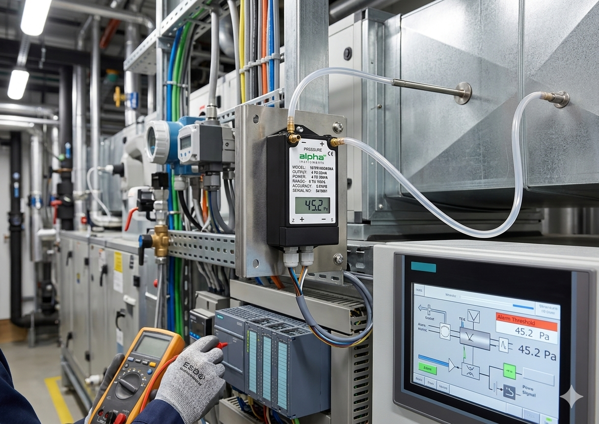
Case 3 – Industrial Paint Booth, Michigan: Airflow Monitoring for Compliance
An automotive parts manufacturer in Detroit operates a spray paint booth that requires continuous airflow verification to maintain compliance with local environmental regulations. The booth’s exhaust fan pulls air through filters and discharges it through a stack. The facility manager needed a way to confirm that exhaust airflow stays above the minimum required level—about 8,000 CFM—at all times when the booth is in use.
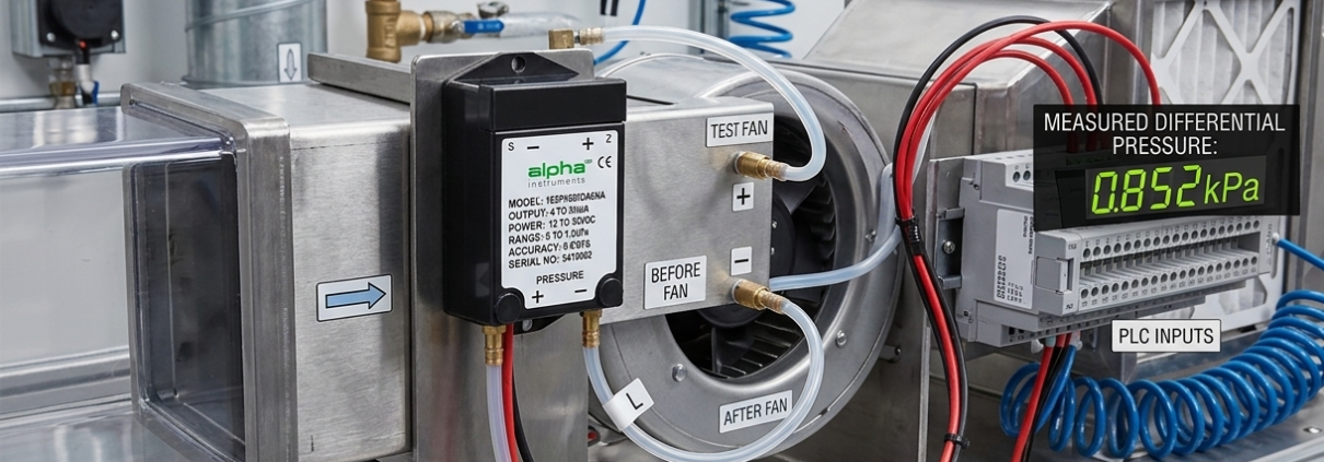
A thermal flow station on the stack was quoted at $4,500. The budget wouldn’t support that. So the facility’s maintenance manager—a guy who had been doing this for twenty years—installed a simple pitot tube in the exhaust stack and connected it to a Model 162 low differential pressure transmitter with a 0-1 inch W.C. range and 0-10V output.
He wired the 0-10V signal into a small PLC that displays the calculated CFM on a screen at the booth entrance. His formula? CFM equals velocity times area. Velocity equals 4,005 times the square root of the velocity pressure from the Model 162. He hard-coded the math into the PLC and set a low-flow alarm to trigger if the calculated CFM dropped below 7,500. Total cost for the measurement system: under $700.
The booth has been running for 18 months. The Model 162 is still working perfectly, and the facility manager has documented flow data for every production shift—exactly what the environmental agency wanted to see during their last inspection.
Why experienced US buyers choose the Model 162: wide range selection (0.10 to 100 inches W.C. unidirectional, ±0.10 to ±50 inches bidirectional), unsymmetrical bidirectional ranges available (most suppliers won’t make these), no glue no organics sensor construction (zero drift over time), three accuracy tiers (±0.25%, ±0.40%, ±0.60% FS), true zero voltage output (no offset to subtract in your BMS), full electrical protection (reverse polarity and miswiring protection), overpressure rating of 15 PSIG, and OEM services with ISO-certified quality.
5. Installation Best Practices—The Things You Don’t Want to Learn the Hard Way
Here’s what I tell every contractor who calls me about installing a low differential pressure transmitter with a pitot tube.
First, get the straight duct run right. ASHRAE recommends at least 5 duct diameters upstream of the pitot tube location and about 3 diameters downstream–. If you install the pitot tube too close to an elbow, a damper, or a transition, the airflow profile will be uneven and your velocity pressure readings will be all over the place. On a rectangular duct, think in terms of hydraulic diameter instead of physical diameter—but for most US HVAC work, 5 duct diameters is the rule of thumb.
Second, mount the low differential pressure transmitter correctly. The Model 162 is designed for surface mounting. Mount it vertically with the pressure ports facing downward. Why? Condensation. When warm air inside the tubing cools down overnight, water droplets can form. If the ports face up, that water runs right into the sensor. If the ports face down, it drips away harmlessly.
Third, keep your tubing runs equal. If one pressure tube is significantly longer than the other, the pressure wave will take longer to reach the low differential pressure transmitter from the longer side, causing a false differential reading. Use identical tubing lengths for both the high and low sides. For the Model 162, 1/4-inch ID tubing is appropriate for most runs.
Fourth, use a shunt valve across the pressure ports if your system can produce overpressure events. Open the shunt valve before starting the system, then close it once system pressure has stabilized—this prevents pressure spikes from slamming the sensor.
Fifth, zero the sensor after installation. Even if the factory calibration was perfect, transportation and mounting stress can shift the zero slightly. For the Model 162, open both pressure ports to atmosphere, let the reading stabilize, and then adjust the zero if necessary. Do this after any configuration change that affects the pressure connections.
Finally, know where the math happens. If your BAS or PLC can take the square root of a raw pressure reading—and most modern systems can—feed the raw 4-20mA or 0-10V signal directly from the low differential pressure transmitter into the controller and let the controller do the math. That’s the simplest approach. If your controller can’t handle square root extraction, you’ll need a transmitter with that functionality built in, or you’ll need to do the conversion in a separate flow computer. The Model 162’s output is a clean linear pressure signal that any modern BMS can work with.
6. FAQs—The Questions I Answer Every Week
Q1: Can I really use any low differential pressure transmitter with a pitot tube to measure airflow?
Yes, but the key is matching the pressure range to your expected velocity pressure. For US HVAC ducts with velocities from 500 to 2,000 FPM, look for a low differential pressure transmitter in the 0-0.25 to 0-1 inch W.C. range. The Model 162 is available down to 0.10 inches W.C. for low-velocity applications.
Q2: How accurate is pitot tube plus low differential pressure transmitter airflow measurement?
With proper installation (straight duct runs, correct pitot placement) and a stable low differential pressure transmitter like the Model 162, you can expect overall system accuracy of ±3% to ±5% of reading in most HVAC duct applications. That’s well within ASHRAE’s recommended tolerance for energy reporting and VAV balancing.
Q3: My velocity pressure readings are bouncing all over the place. What’s wrong?
Three common culprits. First, the pitot tube may be too close to an elbow or damper—remeasure your upstream and downstream straight duct lengths. Second, the airflow might be turbulent due to a poorly designed transition. Third, the low differential pressure transmitter itself may have excessive noise—the Model 162’s stable variable capacitance sensor is much quieter than low-end piezoresistive sensors.
Q4: Do I need square root extraction in my low differential pressure transmitter?
Not necessarily. You can perform square root math in your BMS or PLC, and most modern controllers do this easily. But if your controller can’t handle square roots, look for a low differential pressure transmitter with built-in square root extraction. The Model 162 is a transmitter that outputs linear pressure—designed to work with controllers that handle the math. Make sure you don’t apply the square root twice; that’s a common mistake that will give you obviously wrong readings.
Q5: How do I calculate CFM from the raw signal of a low differential pressure transmitter?
Here’s the full process. From the transmitter, get velocity pressure (ΔP) in inches W.C. Then velocity in FPM = 4005 × √(ΔP). Then CFM = FPM × duct area in square feet. Round duct area = π × r² (r in feet). Rectangular duct area = height × width (both in feet)-23.
Q6: Can I use a bidirectional low differential pressure transmitter for airflow measurement?
Yes, and you may need one if your system experiences flow reversal—for example, in some laboratory exhaust applications or VAV systems with reverse airflow during economizer cycles. The Model 162 offers bidirectional ranges from ±0.10 to ±50 inches W.C., and we can also accommodate unsymmetrical bidirectional ranges (like -0.5 to +3.5 inches W.C.) for applications with an offset zero point.
Q7: What happens if I overpressure my low differential pressure transmitter?
The Model 162 is rated for up to 15 PSIG overpressure with no damage across all ranges-1. For a 1-inch W.C. range, 15 PSIG is roughly 415 inches W.C.—far beyond what you’d ever see in an HVAC duct in normal operation. For industrial applications with potential for high pressure spikes, install a bypass valve or isolation valves on both ports with a shunt valve between them.
Q8: Do I need an ISO-certified low differential pressure transmitter for my job?
Only if the project specification requires it or if you’re working in a regulated industry like pharmaceuticals, medical devices, or semiconductor manufacturing. For standard HVAC work in US commercial buildings, ISO certification is nice to have but not mandatory. We are ISO-certified and can provide documentation on request for those who need it.
Q9: What OEM services do you offer for the Model 162 for volume buyers?
We offer custom pressure ranges (including unsymmetrical bidirectional ranges), custom connectors and cable assemblies, private labeling and custom packaging, firmware configuration (including custom output scaling for your BMS protocol), and ISO-certified quality documentation. One US medical device OEM ordered 3,000 units with a custom ±0.30 inch W.C. bidirectional range—we built them, shipped them on time, and they’ve become a repeat customer.
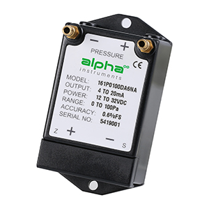
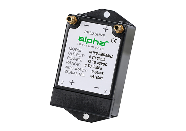
Q10: What’s the difference between the Model 162 and the Model 161?
Both are built around the same stainless steel and glass variable capacitance sensor with no glue or organics—so zero drift over time isn’t an issue with either one. The difference is form factor. The Model 161 has a slightly larger NEMA 1 enclosure, while the Model 162 is more compact and lightweight, making it easier to mount in tight spaces-1. Both units offer the same pressure ranges (0.10 to 100 inches W.C. unidirectional, ±0.10 to ±50 inches bidirectional), accuracy options (±0.25%, ±0.40%, ±0.60% FS), and output options (0-5VDC, 0-10VDC, or 4-20mA). If you need the smallest possible footprint for your installation, go with the Model 162 . If enclosure size isn’t a constraint, either unit will deliver the same excellent field performance—they use the same internal sensing element, so the core measurement capabilities are identical.
7. Bottom Line for US Contractors
Look, I understand the temptation to just spend the money on a commercial airflow station and be done with it. But if you’re doing more than a handful of airflow measurement points on a job—and most of you are—the pitot tube plus low differential pressure transmitter approach is hard to beat. It costs less. It delivers the same ±5% accuracy that ASHRAE accepts for most applications. And with the right transmitter, like the Model 162, it’s extremely reliable.
The Model 162 was built for this. No glue, no organics in the sensor means no drift over time. Wide range selection means you can measure everything from a 500 FPM low-velocity duct to a 3,000 FPM high-velocity exhaust stack. Multiple accuracy tiers let you choose exactly what your application requires. And the compact, lightweight design makes installation faster.
Here’s what we can help with:
-
Free application check – send me your duct size, expected velocity, and BMS type, and I’ll tell you exactly which Model 162 range and output signal to use
-
Pitot tube + low pressure transmitter bundle spec sheet – includes wiring diagrams, CFM formulas, and installation best practices
-
Model 162 samples for testing – OEM buyers get priority
-
OEM services – custom unsymmetrical bidirectional ranges, connectors, private labeling, ISO documentation
-
Volume pricing – call or email me directly to discuss
Visit the product page: Model 162 Cost-effective Differential Pressure Transmitter
Need airflow data but don’t want to blow your budget? Use the contact form on our website. Urgent question about pitot placement or square root math? Call or email. We’re here before you buy—not just after.
One last thing. If you’ve already got a low differential pressure transmitter that’s giving you trouble—noisy readings, drifting zero, inconsistent results—email me the model number and a photo of the installation. Odds are I can diagnose the problem over email. No charge. Just helping US contractors get airflow measurement right.