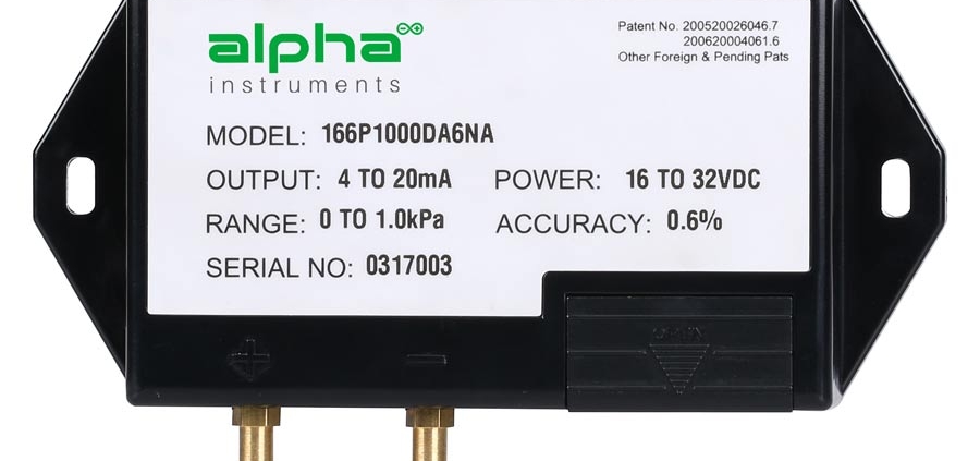
The pressure sensor is a device that can sense the pressure signal and convert the pressure signal into a usable output electrical signal according to a certain rule. It is usually composed of pressure sensitive components and signal processing unit. According to different test pressure types, pressure sensors can be divided into gauge pressure sensors, low differential pressure sensors and absolute pressure sensors. However, there will be some errors in the use of sensors in measurement. Among them, there will be errors in the use of low differential pressure sensors. If there are errors, they will affect the measurement results, so we must reduce these errors when using the sensors. Here’s how to reduce the error when installing low differential pressure sensors.
When in use, the liquid pressure tube should avoid high points, and the gas pressure tube should avoid low points. This is the preparation work to be done in the layout, so that the error can be reduced.
To reduce the error, the two pressure guiding tubes should be kept at the same temperature. At the same time, the caliber should be as large as possible, and the pressure guiding tube should be as short as possible.
There must be no gas in the liquid guide tubes, and the level of the two guide tubes should be the same when the spacer is used.
When the pressure pipe is connected to the process pipeline upward, its slope cannot exceed 1/12. And it’s time to measure liquid vapor on it.
Finally, when the low differential pressure sensor is measuring gas, the pressure guide pipe we refer to shall be connected downward to the process pipeline, in which the required slope shall not be less than 1/12.
Therefore, there are many benefits to the correct installation of the low differential pressure sensor, which is also a skill that every worker must master. The installation is of vital importance to the staff, and it is also necessary to master the wiring method of the sensor. Now let’s talk about how the sensors are wired.
In fact, the wiring methods of various sensors are basically the same. Pressure sensors generally have a two-wire system, a three-wire system, a four-wire system, and some have a five-wire system.
The two-wire system of the pressure sensor is relatively simple. Generally, customers know how to connect it. One wire is connected to the positive pole of the power supply, and the other is the signal wire connected to the negative pole of the power supply through the instrument, which is the simplest method.
The three-wire system of the pressure sensor is based on the two-wire system with a line that is directly connected to the negative pole of the power supply, which is a bit more troublesome than the two-wire system.
The four-wire pressure sensor must be two power input terminals, and the other two are signal output terminals. Most of the four-wire system is voltage output instead of 4-20mA output. The 4-20mA one is called pressure transmitter, and most of them are made into two-wire system. The signal output of some pressure sensors is not amplified, and the full-scale output is only tens of millivolts, while some pressure sensors have an internal amplifier circuit, and the full-scale output is 0~2V. As for how to connect to the display instrument, it depends on the range of the instrument. If there is a gear suitable for the output signal, it can be measured directly, otherwise a signal adjustment circuit must be added.
The five-wire pressure sensor is not much different from the four-wire system, and there are fewer five-wire sensors on the market.


